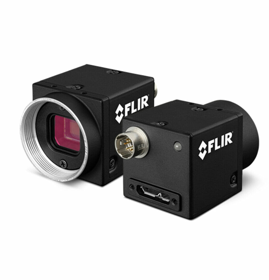
Choosing the right interface for your machine vision application is a key decision in your camera selection process. The following sections provide an overview of the different types of cables and connectors available for machine vision applications along with associated pros and cons.
Machine vision interfaces typically come in two flavors: dedicated and consumer.
Dedicated interfaces
Useful for applications where extremely high-speeds or ultra high-resolution necessitate the use of such interfaces; for example, line-scan cameras used to inspect continuous flow processes like paper or plastic film production where cameras frequently work in the kHz range. However, these interfaces tend to be significantly more expensive, less flexible and add to system complexity. CarmeraLink (supports up to 6.8Gbit/s of data) and CoaXPress (supports up to 12Gbit/s) are dedicated machine vision interfaces typically used in such applications. In addition to the cameras, systems using these interfaces require frame grabbers. These are specialized adapter cards to receive image data and assemble it into usable images. Dedicated machine vision interfaces also use proprietary cables, making integration with other peripherals a little more challenging.
CoaXPress (CXP)
The CoaXpress interface was launched in 2008 to support high-speed imaging applications. CXP interfaces use 75ohm coaxial cables and support data transfer speeds of up to 6.25Gbit/s per channel, with the ability to use multiple channels to support even faster data transfer rates. A CXP cable can supply up to 13W of power per cable and requires that both the ‘device’ and the ‘host’ support the GenICam camera programming interface. While single-lane coaxial cables are inexpensive, the cost of setting up multi-lane cable assemblies and frame grabbers add up very quickly.
CameraLink
The CameraLink standard was launched in the year 2000 by Automated Imaging Association (AIA) and has been upgraded progressively in order to support higher data speeds, with some versions requiring two cables for transmission. The three main configurations available include Base (2.04Gbit/s), Medium (5.44Gbit/s) and Deca/Extended (6.8Gbit/s). The base standard uses MDR (“Mini D Ribbon”) 26-pin connector, while the medium/full configuration doubles capacity using a second cable. The Deca/Extended versions go beyond limits imposed by CameraLink, carrying up to 6.8 Gbit/s of data. Like CXP interfaces, CameraLink requires frame grabbers and additionally need to be compatible with Power over Camera Link (PoCL) standard in order to supply power. CameraLink lacks any error correction or resend capabilities, requiring expensive and cumbersome cable setups to try and eliminate dropped images by maximizing signal integrity.
Consumer interfaces
These interfaces enable machine vision cameras to connect with host systems using widely available USB and Ethernet standards. For most machine vision applications, the USB 3.1 Gen 1 and Gigabit Ethernet consumer interfaces provide a winning combination of convenience, speed, simplicity and affordability. Furthermore, consumer interfaces support widely available hardware and peripherals for machine vision implementation. USB and Ethernet hubs, switches, cables and interface cards can be purchased anywhere from Amazon to your local computer or electronics store at a range of price points to suit your exact requirements. Most PCs, laptops and embedded systems include at least one port each of Gigabit Ethernet and USB 3.1 Gen 1.
The most obvious difference between these categories of interfaces is their bandwidth. Faster interfaces enable higher framerates (Fig. 1) for a given resolution. A faster interface enables you to capture more images each second or capture higher resolution images without sacrificing throughput.
For example, a semiconductor wafer inspection system being upgraded from 8” to 12” wafers, higher resolution cameras will be required. In this case, the system designer will need to choose between keeping their existing interface and trading higher resolution for reduced throughput, or upgrading to a faster interface to maintain, or improve the throughput.
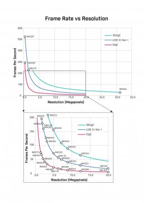
Fig. 1. Bandwidth available for each interface vs. sensor resolution and the resulting frame rate.
Your requirements for resolution, frame rate, cable length and host system configuration should all be considered to ensure you get performance you require without spending more than you need. FLIR’s machine visions cameras support all three trusted and widely available interfaces.
Universal Serial Bus (USB)
USB is everywhere. Look around and count the number of USB devices and accessories around you. See what we mean? Most USB machine vision cameras use the USB 3.1 Gen 1 interface. This interface provides up to 4Gibt/s of image data bandwidth between the camera and the host system. The USB3 Vision standard helps ensure compatibility between a wide range of cameras and software by defining a common set of device detection, image transfer and camera control protocols.
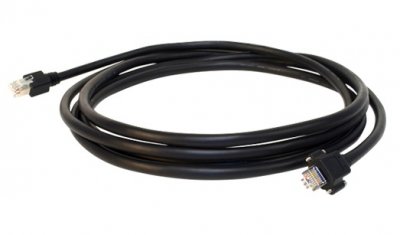
Fig. 2. USB 3.1 Gen1 cable (USB to locking USB)
USB supports Direct Memory Access (DMA). With this DMA capability, image data can be transferred across from the USB directly into memory where it is available for use by software. DMA coupled with the widespread support for USB and availability of drivers for USB controllers on virtually any hardware platform makes USB ideal for use in embedded systems. The 5m maximum cable length of USB 3.1 Gen 1 is generally not an issue for embedded systems. USB 3.1 Gen 1 can simplify system design by supplying up to 4.5 W of power to a camera. The recently developed USB Power Delivery specification allows some hosts to supply more power to devices like rapid-charging mobile phones, this specification is independent from the base USB 3.1 Gen 1 standard and has not been adopted by machine vision camera manufacturers.
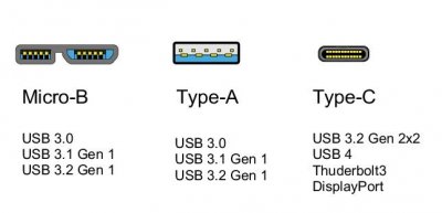
Fig. 3. Different types of USB connectors
High-flexibility USB cables help maximize the lifespan of cables in systems where the camera must be moved repeatedly. Active optical cables (AOCs) may be used to greatly extend the working distance and provide Electromagnetic Interference (EMI) resistance. The performance of active optical cables is dependant on the throughput requirements and the host system configuration. When using optical cables, even those that supply power via the cable, FLIR recommends using powering cameras externally via GPIO. Additionally, locking USB cables provide a secure connection between cables, cameras and host systems. Prior to purchasing locking cables, FLIR recommends checking the locking screw position and spacing compatibility, as several options are available.
USB 3.1 Gen 1 is available on FLIR Blackfly S – Cased and Board level versions, and the tiny Firefly S.
Gigabit Ethernet (GigE)
GigE provides up to 1Gbit/s of image data bandwidth. Its combination of simplicity, speed, 100m maximum cable length and ability to supply power to cameras over a single cable make it an extremely popular camera interface. Ethernet cables are available with robust shielding. This is ideal for environments with high electromagnetic interference caused by proximity to the powerful motors found in some robots and metrology equipment. FLIR GigE cameras also support a packet resend feature which further boosts transmission reliability.
Unlike USB, GigE does not support DMA. Packets containing image data are transmitted to the host where they must be reassembled into image frames prior to being copied to software accessible memory. This process is trivial for modern PCs, though it may result in latency for some low-power embedded systems with limited system resources.
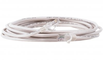
Fig. 4. Gigabit Ethernet / GigE Cable (RJ45 to RJ45)
The widespread adoption of Gigabit Ethernet means there is an incredibly wide range of supporting products from cables to switches, ready to meet any project requirement. GigE cameras support the IEEE1588 PTP time synchronization protocol, enabling cameras and other Ethernet enabled devices such as actuators and industrial Programmable Logic Controllers to operate on a precisely synchronized common time base.
The widespread adoption of Ethernet across many industries has enabled availability of many specialized cables and connectors for a wide range of use cases. For example, there are Ethernet cables designed to protect against EMI (Electromagnetic Interference), high temperature and chemical resistance, while some cater to high flexibility requirements and so on.
Ethernet cables have a category number depending on their construction. CAT5e is the most common for GigE, while CAT6A, CAT7 and CAT8 may be used for additional EMI resistance at the expense of greater cost and increased cable diameter. Some industrial devices use an X-Coded M12 (Fig. 3, right) connector to provide increased shielding, however, for most applications, the familiar RJ-45 connector is good enough and provides greater convince at lower cost. Additionally, screw locking RJ45 connectors easily add additional security to RJ45 cables.
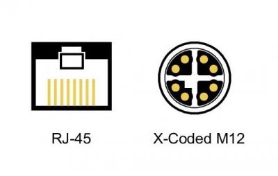
Fig. 5. The ubiquitous RJ45 connector (left) and the less common X-Coded M12 connector (right)
Note: RJ45 connector is quick to connect and disconnect. X-Coded M12 connector (right) is slower to connect, but more robust and available in IP rated versions.
GigE is available on FLIR Blackfly S – Cased and FLIR Blackfly S – Board Level Cameras.
10Gigabit Ethernet (10GigE)
10GigE builds on the strengths of GigE by increasing the bandwidth to 10Gbit/s. 10GigE is an ideal interface for high-resolution 3D scanning, volumetric capture and precision metrology. GigE and 10GigE can be combined in numerous ways. Multiple GigE cameras can be connected to a 10GigE switch to support multiple GigE cameras at full speed over a single 10GigE port on a host system. While CAT5e cables will work with 10GigE cameras over distances less than 30m, CAT6A or higher cables are recommended.
10Gbit/sec is a lot of data! Modern PC systems with high-speed CPUs, PCIe 3.0 and dual channel memory can handle this well, while higher performance systems can support multiple 10GigE cameras. Embedded systems with reduced system resources will generally lack the memory bandwidth and processor speed required to keep up with the incoming image data.
10GgiE is available on FLIR Oryx cameras.
Summary
Both consumer and dedicated interfaces are used across many machine vision applications. Pros and cons mentioned in previous sections would eventually determine the suitability of one over another for a specific use case. However, the combination of performance, ease of use, widespread availability and low cost make consumer interfaces an attractive choice for most machine vision applications.

