Casper, Phillips & Associates Inc. (CPA) has designed and installed a bespoke fall protection system for a large commercial airplane supplier.
CPA was contracted to integrate it with 67 separate bridge cranes that vary in capacity from 34 tons to 40 tons and cover three million square feet. The galvanized chain-link (ASTM A392-07) installation allows crane operators and maintenance personnel to transition from a 90-ft.-high catwalk to crane bridge egress platforms without wearing personal protective equipment (PPE), which involved the time-consuming process of attaching and disconnecting harnesses etc. Overall dimensions of the frames are 10 ft. 5 in. by 35 ft. 1 in.; the bridge girders are 12 ft. on center; and the chain link area is 7 ft. 6 in by 9 ft. 2 in.
Richard Phillips, mechanical engineer at CPA, said: “It was a voluntary upgrade. The bridge egress platforms were not previously equipped with fall protection. It’s not that the [safety] codes changed; the owner wanted to no longer require that workers be tied off. Maintenance personnel work at height to perform routine upkeep, such as greasing bearings, changing gearbox oil, and replacing the hoist wire rope. Crane operators access the bridges via catwalks and only use the egress platforms if the bridge or cab breaks down—or if there is an emergency.”
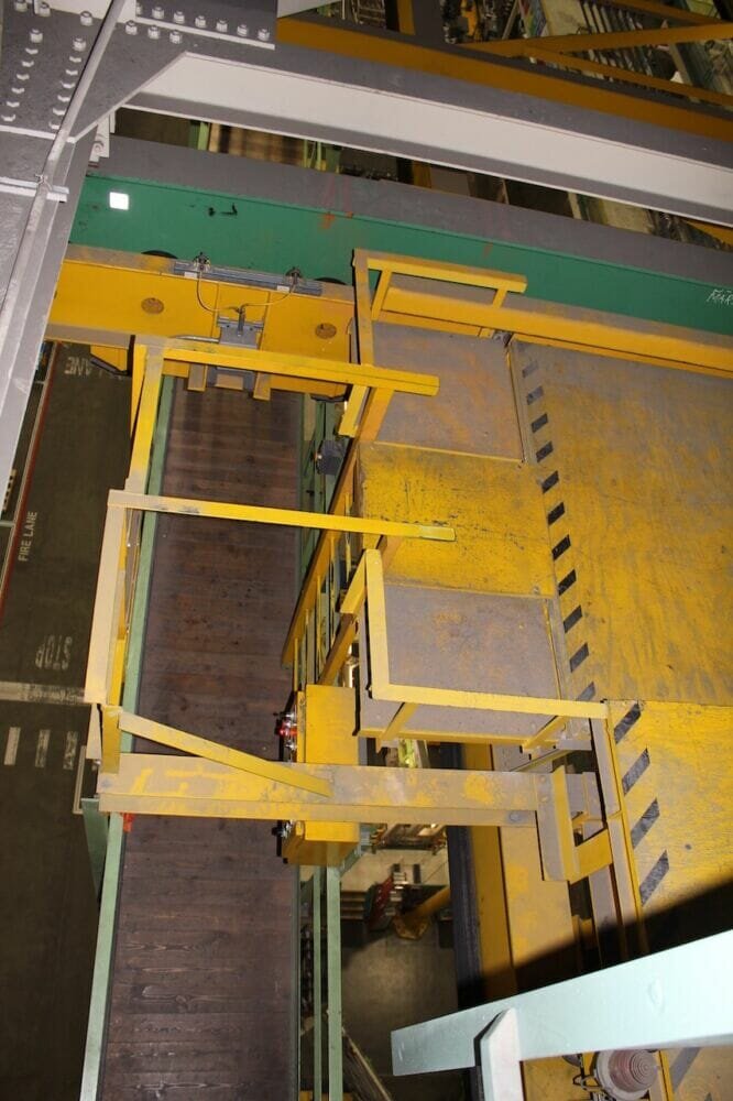
This photo is taken from the factory (house) catwalks and is looking down to the bridge catwalk. There is a ladder from the bridge to the lower egress platform. 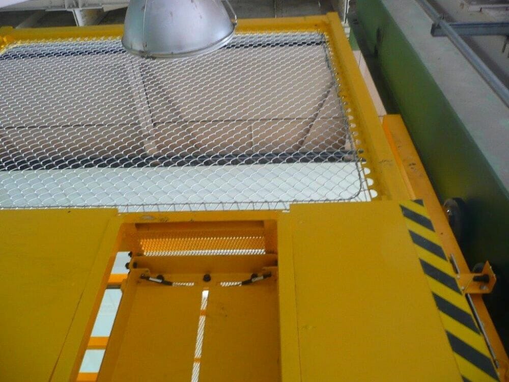
The installation allows crane operators and maintenance personnel to transition from a 90-ft.-high catwalk to crane bridge egress platforms without PPE.
Phillips explained that the crane bridge spans vary between 100 ft. and 150 ft. Lift heights are all approximately 67 ft., he added. A low-weight solution was needed to not structurally impact the bridge and rail system. The CPA net frames offer the added benefit of allowing workers to see through them. A solid platform would have also been considered a working surface, which would have still required additional guarded edges for fall protection. The system was tested by dropping a 400-lb. sand bag from a height of 55 in.
The factory was divided into two halves—the old and new part of the factory. The new area had a frame system that slipped in around the existing egress platforms, while the older half required the existing egress platforms to be removed and new platforms integrated into the net frame. The old half had much shorter bridge bumpers and the net frame was designed to overlap from an adjacent bridge so the bridges could still go bumper-to-bumper. No two net frames across the factory were the same because conduit, junction boxes, lacing, and as-built egress locations varied from one bridge to another. The chain link to frame interface was consistent for all net frames.
3D scanning technology
Andrew Hanek, a civil engineer at CPA, said: “The project was unique because of the time constraints required to install the frame and no two bridges were alike. They all appear alike at first sight, but the location and orientation of limit switches etc. always changed. As-built conditions of things like the ladder and ladder cage changed or had angles mounted backwards. Space limitations were also a huge concern since the bridges still had to go bumper-to-bumper for picks and we had minimal clearance vertically with the roof truss system.”
Many of these differences were either inadequately documented or not documented at all. CPA decided that the best path forward was to leverage handheld 3D scanning technology and scan all the cranes for these minor differences. CPA created a primary design that could be slightly modified to fit each crane without any costly interferences. As Phillips said, “A minute in the shop is worth five minutes in the field so it was very important that everything dropped in and fit to minimize downtime.”
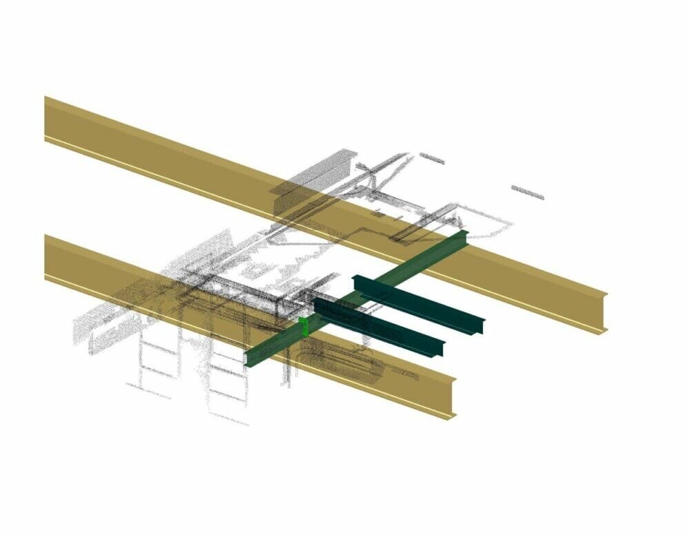
The point cloud data shows existing items. The net frame that goes around the egress platform is the new net frame. 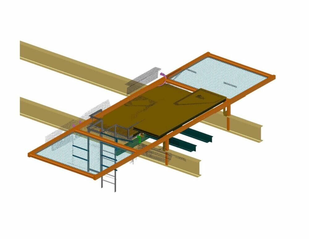
CPA decided to reference the point clouds to the bridge girder and assume that the 12-ft. on center spacing was precise.
The bridges were scanned from the bridge and factory catwalks, a maintenance trolley for areas between the bridge girders, and the top of the egress platforms. The top of the platforms did not have a lot of unique features so stitching the point clouds across the platform did not give good results. CPA decided to reference the point clouds to the bridge girder and assume that the 12-ft. on center spacing was precise. This method, combined with photos, allowed CPA to identify all features of concern to work around.
The majority of point cloud scanning and data processing into 3D was performed by Hanek.
Installing the bespoke fall protection system
“The first few bridges were a learning curve,” Hanek acknowledged, “But the installation crew eventually got it down to the entire process for a single bridge being performed in a 12-hour window. Net frames were fabricated and staged ahead of time so they could be hoisted into place and installed. If needed, relocation of electrical conduit and junction boxes was performed prior to the frame installation. The short install time was a huge success since production was not able to lose bridges for days at a time. All work was performed between shifts and pick moves while the factory remained at full production.
- The relevant safety code for the galvanized chain-link installation is Chapter 296-155 WAC Construction Work.


