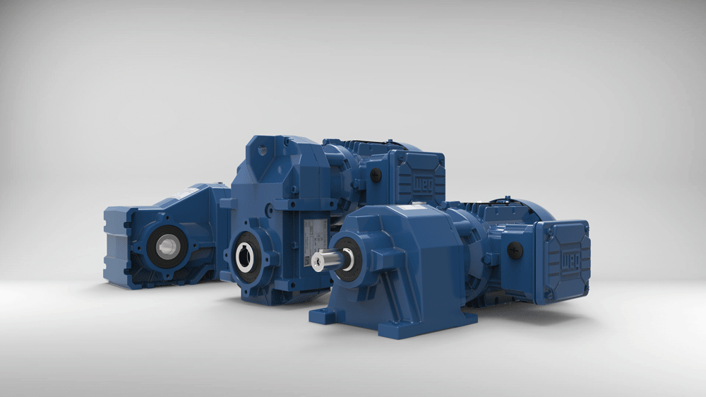
~ Understanding the different gear technology choices ~
Despite being responsible for gear selection, engineers and plant operators are often not experts in gear technology. Plus, the information that is out there is not always clear or correct. Here, Marek Lukaszczyk, European and Middle East marketing manager of gearbox, motor and drive manufacturer WEG, explains each gear type and simplifies the decision-making process.
Gears are among the most important components in a wide variety of drive trains, transmitting the right amount of movement and force to ensure the smooth running of a machine. However, engineers require a complete understanding of the basic principles and suitable applications of each gear type.
Today, the development of gears and geared motors is at an extremely advanced stage. Improvements to materials, designs and efficiencies have largely been exhausted, meaning it is more likely that new developments will be seen on the electronic side. Engineers must understand how these machine components will integrate into their application and the overall digital factory package.
Helical gears
There are five gear types that engineers need to be aware of, these are helical, parallel shaft, bevel, worm and planetary.
Helical gears are the common types of gear wheels, with a distinction made between the different types of gearing. The simplest is straight cut gears. As a rule, this type of gearing uses involute helix gearing. If larger torques are to be transmitted, helical cut gears are used for the gear unit design. These run more smoothly on each other, enabling quieter running gears.
However, the disadvantage of helical cut gears is that they generate axial forces, which in turn must be absorbed by the bearings of the gear unit. In this case, this requires bearings that can absorb both radial and axial forces.
Helical gearmotors are utilised in a multitude of applications including presses, conveyors, rotary tables, pumps, packaging machines and bakery equipment.
Parallel shaft gears
Parallel shaft gearboxes also utilise helical gearing, but in contrast to conventional helical gear units, the input and output shafts are offset parallel to each other.
Due to this design, the axial dimensions of the parallel shaft gear unit are compact, helping to save space. Additionally, these are usually multi-stage helical gear units with parallel shafts, comprising an output shaft which is usually a hollow shaft, allowing the gear to be mounted on an existing shaft.
Typical applications for parallel shaft gearboxes include screw conveyors, extruders and travel drives.
Bevel gears
Bevel gears are characterised by the axes not being parallel to each other and are used to transmit power to two axles spinning at different speeds, such as lift applications. In principle, any axis angle can be achieved with bevel gear wheels. In most cases, however, the input and output axes are at an angle of 90 degrees to each other.
Bevel gears are often combined with helical gearing in industrial gearmotors, with wide areas of application including agitators, winches, lifts, heavy-duty conveyors for bulky goods, shredders and baggage handling systems.
Worm gears
The worm gear units consist of the worm and the worm wheel, meaning a high transmission can be achieved in a small space. A worm can be imagined as a screw, with the number of teeth in the gear wheel corresponding to the number of gears in the worm.
However, due to the friction that occurs on the flanks of the worm and worm wheel, the efficiency of the gear unit is lower compared to helical gears. These high thermal losses necessitate good lubrication and sometimes additional cooling for high power outputs to counteract this problem.
Worm gears are widely used in applications such as elevators, lifts, packaging machines and light conveyors.
Planetary gears
Gear wheels with fixed axes of rotation are called central or sun gears, while the non-stationary gear wheels are called planetary gears.
Planetary gears are available in many versions with various transmission ratios, depending on the shaft where the output takes place. A distinction is made between gear units with fixed ring gear, fixed sun gear, fixed rack or direct drive.
The gear arrangement typically provides a high torque density and precision, with wide-ranging fields of application, including wind turbines, track drives, crushers, shredders and robotics.
Other considerations
When selecting which gear type, engineers should also know what loads the gear unit will be exposed to and the environmental factors it will be exposed to. These include space requirements such as drive output, drive control and other ambient conditions that must be considered, especially when retrofitting. This is because installing a gear unit should not require design changes to the existing machine or system.
While it is easy to find a lot of information about gears, remember it is not always clear or correct. That is why WEG published a free gearbox guidebook, titled What mechanical engineers and plant operators need to know about gears, to ensure engineers choose the appropriate gear for their application and quash a few misconceptions.
Further information on WEG’s gearboxes can be found on the company website.


