- Why are DC-Link capacitors so crucial?
- Design factors that affect the choice of an inverter DC-Link capacitor
- Capacitors for challenging inverter designs
DC-Link capacitors are an important step in power conversion for a number of uses, including three-phase Pulse Width Modulation (PWM) inverters, wind power and photovoltaic inverters, motor drives for industry, onboard chargers and inverters for cars (Figure 1), medical equipment power supplies, etc. Some of the most challenging applications entail rigorous environmental constraints as well as requirements related to costs and reliability. In the case of circuit designs, various approaches are used, but power conversion designs typically include DC-Link capacitors. DC-Link capacitors enhance energy density in the system and offer a solution to the physical problem of ripples caused by rapid switching that is inherent in switching power conversions. Which capacitors should be selected as DC-Links, and what makes them a good choice?
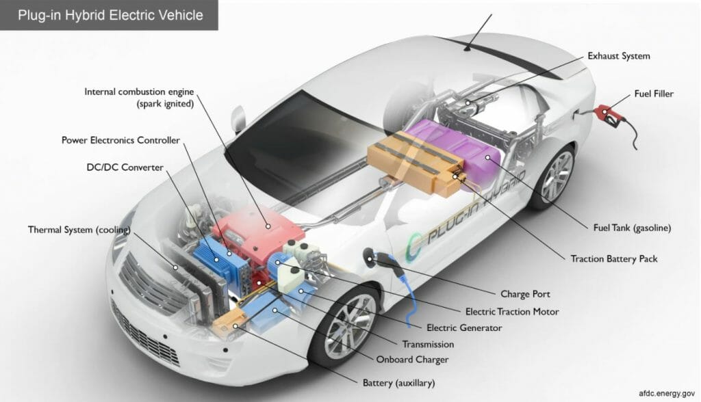
Figure 1: DC-Link capacitors are crucial components in power conversion design for a number of inverter applications, for instance hybrid electric and electric vehicles. Together, HEVs and EVs will have grown to an estimated 30% of total vehicle sales by 2025, according to JP Morgan Chase and Company. (Image source: afdc.energy.gov)
In fact, the automotive industry offers a very good example of power conversion in the hybrid and electric powertrain. Battery-powered electric cars have a rechargeable bank of batteries which store energy for the drive system, the electric drive motor, and the power controller that includes an inverter. All of the above require high voltage, from 48 VDC to even 800 VDC. Due to the physical restraints that limit current, high voltage entails high performance. The higher the operating DC voltage, the lower the current flow that is needed for the same power output (P=VI). It is common knowledge that the automotive industry demands components that will operate with exceeding reliability at very high temperatures, under continuous vibration, and in harsh environmental conditions. The three-stage traction inverter converts battery power to drive the motor, with the DC-Link capacitor being a crucial component in this design.
Electric vehicles operate in a different way than toy cars, as they do not use energy stored in the battery pack directly. Instead, energy has to be converted. A typical 3-stage power inverter for a hybrid/electric vehicle (HEV/EV) consists of:
- The input stage from the battery pack that outputs a DC voltage (Stage I).
- A DC-Link capacitor filters and smooths out DC voltage on the DC bus rails and begins conversion (Stage II)
- Conversion starts via high-frequency switching (with output much like a rectifier to the rails) and the inverted power is provided to the load as the load generates instantaneous demands (Stage III)
WHY ARE DC-LINK CAPACITORS SO CRUCIAL?
The task of the DC-link capacitor is to balance the fluctuating instantaneous power on the rails which results from the activity in Stage I and Stage III. The DC-Link capacitor smooths out the “ripple” created by high-frequency power switching circuits in Stage III. The total sum of Root Mean Square (RMS) alternating and direct current/voltage that a capacitor can withstand without failure is the ripple current/voltage (defined at a specific frequency and temperature).
How is the capacitance needed for smoothing out voltage spikes calculated?
The voltage and current on the rails must be balanced and smoothed out by the DC-Link capacitor located in Stage II (in fact, this involves decoupling spikes that result from switching). In order to determine the necessary minimum capacitance and ripple voltage, you can use the following equation:
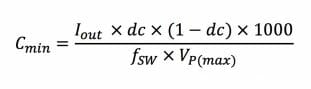
where Cmin = required minimum capacitance, Iout = output current, dc = duty cycle, fSW = switching frequency, VP(max) = peak-to-peak ripple voltage.
DESIGN FACTORS THAT AFFECT THE CHOICE OF AN INVERTER DC-LINK CAPACITOR
DC-link capacitors are used in order to provide more stable DC voltage and limit fluctuations, as the inverter demands heavy current sporadically. With a number of various technologies used in DC-Link capacitors, there is a choice of numerous versions available, e.g. aluminum electrolytic, film, and ceramic capacitors. The choice of the best solution is highly dependent on the application.
The first step in selecting a DC-Link capacitor is to compare such values of rated capacitance and voltage that will satisfy energy requirements, but at the same time help avoid high ripple current. Ripples at DC-Link nodes, mainly caused by incredibly fast-switching IGBTs or MOSFETs in Stage III, influence performance, as all real capacitors have a certain amount of impedance (and self-inductance). Moreover, it is a task of a DC-Link capacitor to regulate voltage and absorb current ripples.
A ripple causes fluctuations in the voltage level in the DC-Link capacitor, as the ripple of the switching current passes through the capacitor (V=IR). Inverter switching frequencies that a DC-Link capacitor has to be able to withstand must also be considered. For example, if the switching frequency exceeds 1MHz, film capacitors will not operate correctly. The required value of DC voltage at the rails, the expected life span of the application, the maximum potential ripple current and frequency that the system will encounter, and whether the ripple current has a steady or intermittent characteristic, are other factors that should be taken into account when selecting a DC-Link capacitor.
Technical data of good DC-Link capacitors should testify to low self-inductance, very low ESR (Equivalent Series Resistance – capacitor’s total internal resistance as specified at a given frequency and temperature), and high ripple current tolerance, all at comparable working temperatures and frequencies among the components that are compared. The lowest possible Equivalent Series Resistance will minimize the heat that is cast-off as dissipated power (PDissipated =I2 x ESR). Nevertheless, in the case of DC-Link film capacitors, Equivalent Series Resistance is significantly lower, but on the other hand it provides a reasonable CV (capacitance voltage) rating, which usually offers a far better response to ripple current.
This means that DC-Link film capacitors allow for high ripple current and longer life expectancy than electrolytic capacitors, and at the same time provide higher capacitance than ceramic capacitors. The actual ripple current rating requirement, however, cannot be predicted easily. Its value is not fixed as it depends on the switching frequency and the harmonics caused by the input and output stages (Stage I and III). The part that sinks or sources the respective currents is the DC-Link capacitor. Other solutions may display a more triangular waveform of the current.
Generally speaking, following changes in the working temperature or applied frequency and voltage, nominal capacitance values may also change. Some other variables that must be considered include the self-inductance that can greatly reduce the impedance of a capacitor at high frequencies, and by doing so it can affect its expected behavior. For any type of a capacitor applied, noise suppressors, e.g. Flex Suppressors® by KEMET, will be useful when it comes to attenuating high-frequency noise caused by the external environment.
Moreover, the capacitor’s Equivalent Series Resistance is quite often responsible for the restraints that limit the ripple current rating (i.e., the ripple current that can be tolerated by the capacitor without overheating). In order to obtain the required low Equivalent Series Resistance and a long lifespan at high dissipation, the physical dimensions of a film capacitor are so big that it frequently turns out that the capacitor already meets or even exceeds the voltage ripple or hold-up time calculations.
Eventually, in the case of any high-power design, one must take into account whether (and what type of) proper cooling is ensured. The ambient temperature profile is one of the critical factors in choosing the best DC-Link capacitor.
CAPACITORS FOR CHALLENGING INVERTER DESIGNS
Currently, several types of capacitors are available on the market, but not all of them can be incorporated into high voltage inverters. In fact, the choice of adequate multilayer ceramic capacitors with the required voltage and temperature rating is rather limited. Electrolytic capacitors may be a quite reasonable choice for a DC-Link application, but not all electrolytic capacitors will be suitable for that purpose. In the past, conventional film capacitors were restricted to lower operating temperatures, but in their case technology has been progressing much faster than the electrolytic technology. Most recent film capacitors, e.g. the C4AE model by KEMET respond to design-related needs much better than their predecessors. Metallized film capacitors have a smaller footprint than electrolytic ones while maintaining similar functionality. While using a large electrolytic capacitor may indeed result in achieving voltage stability, such sizeable components will at the same time, for example, decrease the power density of an automotive inverter. The size and weight of components definitely affect the overall efficiency and value of the vehicle.
Film capacitors also offer a longer life span than the electrolytic ones, mainly thanks to the fact that in the case of the former type, layers of metal are vapor-deposited over a substrate. An internal short-circuit can be self-corrected due to high energy levels deposited between the ultra-thin layers of aluminum, and minor faults are simply vaporized within microseconds, without interrupting performance in a noticeable way. As they can tolerate rapid overvoltage and transients, film capacitors are also ideal for high-voltage pulsing applications and related safety concerns. Film capacitors are not polarized, they can provide a longer working life (which can be even more prolonged by means of derating), greater current capacity, reliable operation over a broader temperature spectrum, and have improved mechanical efficiency when compared to electrolytic capacitors. Their other advantages include a wide choice of mounting methods. Moreover, rugged film capacitors are available at voltage bus levels exceeding 500VDC, which is very significant in the case of hybrid/electric vehicle applications.
A great example of a film capacitor which is suitable for hybrid and electric vehicles is the C4AQ film capacitor by KEMET, which is AEC-Q200 rated for HEV/EV applications and offers some important qualities that will work well in DC-Link architectures. As we have already read, C4AQ capacitors by KEMET feature all the superior advantages of film capacitors. Alternatively, KEMET’s C4AE power film capacitors are available, which are similar to the C4AQ, however, they are not graded for automotive applications. Other solutions that are suitable for non-automotive DC-Link applications include CKC Ceramic KC-LINK as well as C44U and C4DE can film capacitors.
In order to ensure successful operation of high power inverters, monitoring may prove to be very important. It should be mentioned that KEMET’s CT series of high current sensors enable real-time current measurement in a live wire.
As you can see, choosing the best DC-Link capacitor for your application is quite a challenging, but also very important task. KEMET, together with TME, offers the products and staff needed to facilitate this process.