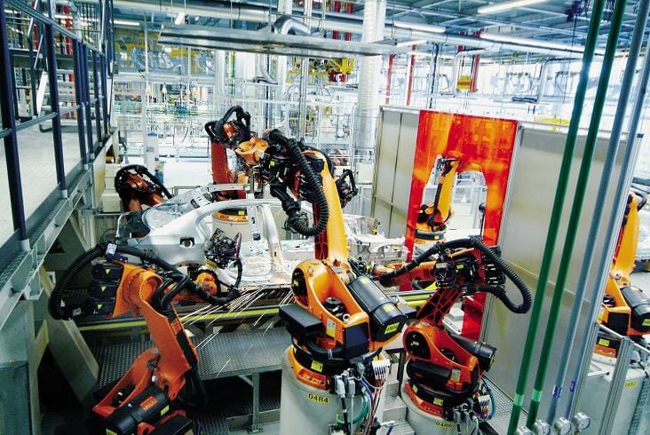
Industrial robots have a key role to play in manufacturing, assembly and packaging operations. Most robots today incorporate servo motors for direct drive operation – an approach that largely eliminates the need for clutches, but that still requires brakes, says Mark Checkley of KEB Automation.
There are two primary reasons why brakes are required for industrial robot applications. First, the brake is used as a holding brake. In normal operation, the brake is engaged at zero speed and used to hold the robot arm or mechanism in place. The second purpose of the brake is to dynamically stop and hold position in the event of power loss in order to avoid harming nearby operators or equipment. When selecting a power-off brake for these types of applications, permanent magnet brakes or spring applied brakes are suitable.
Is safety critical?
In many robotic applications, permanent magnet (PM) brake technology is attractive because it offers higher torque density (torque per diameter) compared to spring applied brake technology. PM brakes also offer zero-backlash performance. Spring applied brake technology, however, is the only true failsafe mechanically-engaged solution available. In applications where safety is critical, a failsafe solution is often non-negotiable. Some examples include an AGV or forklift truck operating in a production plant with employees walking around, or a medical boom in an operating theatre that is holding expensive and dangerous medical equipment in close proximity to patients and doctors, or a robotic pick-and-place arm on an assembly line.
Other key factors to consider
The requirements for industrial robotic applications vary widely. Key factors to consider include:
- Torque – this is the torque required to stop or maintain the static position of a robot. This depends on weight, structure, load and velocity.
- Backlash – this is defined as the amount by which the shaft will rotate while the brake is holding. This lost motion depends on the hub used to connect the shaft to the brake. The hub must provide sufficient clearance to enable the armature to move axially along the shaft. As a result, a spring-applied brake will always have some degree of backlash. The level of acceptable backlash depends on the application. For high precision, high accuracy applications, permanent magnet (PM) brakes offer zero backlash performance. Examples include semiconductor fabrication and medical device manufacturing. For most other industrial applications, spring-applied brakes will perform effectively and at a reasonable cost.
- Bore diameter – brakes for robotic arms need through-holes to allow the passage of cables, lasers and fibre optics. Typically, PM brakes provide the largest bore diameters, followed by spring-applied tooth brakes.
- Torque-to-diameter ratio – robots are normally constrained by the space they operate in, which means the torque-to-diameter ratio is a key consideration. In general, OEMs should look for the highest possible ratio, particularly for the brakes used at the base of the robot arm.
- Response time – power-off brakes are typically used as safety brakes that engage when power fails. In this case, response time is particularly important. PM brakes tend to have the faster response times and so are often the prefeered choice in safety-critical applications.
- Resolution – robots provide highly controlled motion and so resolution is always important. Both PM brakes and spring-applied brakes offer infinite resolution.
- Cost – spring-applied friction brakes tend to be the most economical solution, offering effective performance in a wide range of applications. PM friction brakes are next in terms of cost, followed by spring-applied tooth brakes – the most costly due to the precision manufacturing required for the tooth interface.
Low profile brake designs
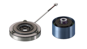
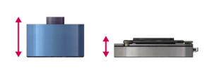
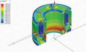
Recent advancements have enabled robotic arms and mechatronic systems to shrink in size. This reduction in footprint often requires low profile or ‘pancake’ style brake technology. KEB has recognised the increasing demand for compact spring applied brakes and has successfully designed custom low profile brakes. This style of brake is functionally identical to the standard spring applied brake but achieves the same rated torque in approximately two-thirds the thickness, which allows for highly compressed drive system braking in robotic joints, AGV’s, forklift trucks, etc. Magnetic simulation software can also be used to design custom brakes that meet customer-specific design envelope constraints.
Incorporating the brake or having it separately?
Not all robotic applications require the brake to be incorporated into the robot arm, which means the size of the brake itself is less critical. In some cases such as torque motors or hollow shaft motors, the brakes will have to be mounted separately. However, size of the brake is still important for all applications.
Application of max and min torque
In medical units such as a surgical operating arm, the brake can also act as the clutch. The brake holds the robot arm in place but if the maximum torque limit is reached, the unit can be moved (i.e. pushed out of the way) but still held safely. Often, the friction material can affect or control this, which is a good safety aspect.
Other common brake design options
Other features can be added to brakes used in compact robotic applications. These include:
- Reduced holding voltage – after being released at nominal voltage, some manufacturers of spring applied brakes can drop to a holding voltage of 50% nominal. This is very advantageous for an AGV, forklift truck or other mobile robotic application where the power supply is a battery, as power consumption is significantly reduced. This will also reduce heat generated from the brake coil. This is typically achieved with PWM (Pulse Width Modulation) controlled by the customer.
- Cable assembly and connectors – some suppliers can provide brakes complete with heat shrink tubing, wire jackets, pig tailed leads, cable labels, etc. Along with added connectors or plugs. This eliminates the need for customers to add cable assembly to their process and provides a ‘plug-and-play’ ready solution.
- Custom coil voltages – some batteries and control systems operate at voltages outside of the common standard offerings (24, 48, 105, 205VDC). Some suppliers can design and wind a coil to suit any desired voltage.
For more information on spring applied brakes or permanent magnet brakes from KEB, please visit www.keb.co.uk

A low profile brake (left) compared to the size of a standard electromagnetic brake (right).

General size comparison between a standard size (left) and a low profile electromagnetic brake (right). Low profile designs reduce thickness by approximately a third.

KEB uses magnetic simulation software to optimise custom brake designs.


